Stale Data from Another PLC Looks Real: A Link Checklist
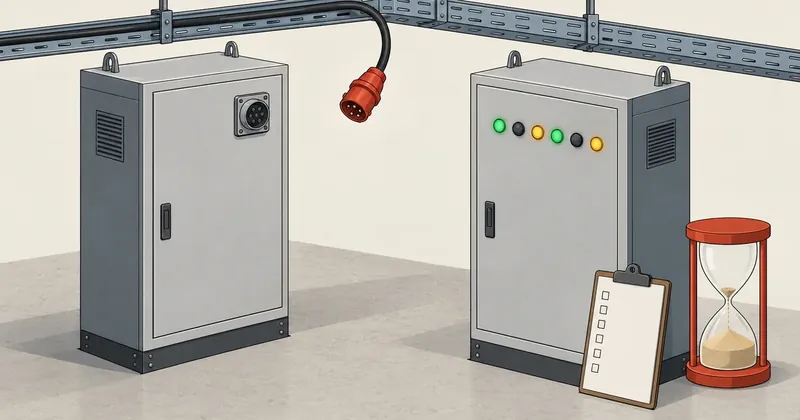
A node that drops off the network does not send incorrect values. It simply stops sending, and the last values remain in the receiver's memory with nothing to mark them as stale.
1-minute summary
- Symptom / problem
- When the sending PLC drops off, the receiver keeps the last value and it looks like live data.
- Who should read
- Anyone building PLC-to-PLC links with TSEND_C and TRCV_C.
- Fix in short
- Use the 11-point checklist, set the timeout from what the process can tolerate, and read STATUS and T_DIAG to tell stale data from live.
I was reviewing a data link I had written between two PLCs using Siemens TSEND_C/TRCV_C blocks. One owns the logic, and the other is a station that receives commands to drive outputs. They send entire DBs to each other cyclically. At first, I thought the link was complete because it had a heartbeat and watchdog built in. But when I asked myself what "complete" meant for a PLC-to-PLC link, I could not answer because I had nothing to compare it against. So I opened the official manuals for Omron's packaged networks to see what their products provide out of the box, then compared those features with my own link one by one. It turned out that what I thought was complete was missing several things.
I need to state the level of evidence first. Everything about Omron in this article comes from the manuals; I have not tried it on real hardware. I measured the STATUS and T_DIAG values from the Siemens communication blocks myself on a simulator, not on a physical PLC. All PLC names, DB names, and variable names in this article are generic. Page references are PDF page numbers, not the numbers printed on the pages.
Timeout values, output states when the link is lost, and automatic resumption when the link returns affect the safety of people at the machine. The numbers in this article come from a single experimental link. They can serve as an inspection framework, but for a real installation, the engineer responsible for the machine must assess the risks and sign off. Safety interlocks, such as emergency stops, must use hardwired circuits or a dedicated safety system, rather than relying on the data link.
Stale Values Look Exactly Like Live Values
The sentence that made me stop reading and go back to my own program was in Omron's Controller Link Units Operation Manual (W309-E1-12), on PDF page 235. A note at the end of the command for reading data link status says:
Any node which is not active in the network retains the status that existed
immediately prior to the generation of the communications error.
Taken literally, this means that a node no longer active on the network retains the status it had before the communications error. Nothing is cleared to zero. There is no special value indicating that the data is dead. A bit that was 1 stays 1. A number that was 137 stays 137. The receiving program keeps using those values to decide outputs as though nothing happened.
A custom raw TCP link on Siemens behaves the same way. TRCV_C writes to the receiving DB only when data arrives. When the other side stops sending, whether because a cable is disconnected, the CPU enters STOP, or power is lost, that DB stays at its last values. Nothing clears it for you. Sending entire DBs cyclically with TSEND_C/TRCV_C acts like a custom Data Link, and it inherits the same stale-value behavior in full.
The diagram shows that the dangerous interval is not after the watchdog expires. By then, the program knows. The dangerous interval is between the node dropping off and the watchdog expiring. In my link, that is 3 seconds. Throughout that interval, the DB contains stale data, but PeerOK is still TRUE. This is why a data freshness indicator is necessary, and why the timeout must be chosen deliberately, which I will cover in the next section.
5 Features Packaged Networks Provide Built In
As I read further through the Controller Link and DeviceNet manuals, I identified at least 5 features they provide without the user having to write them.
- Per-node Data Link status with 4 bits per node: PLC status (whether the program is running), CPU Unit error, Communications error, and Data link participation. Selecting the 8-bit format adds the 3 flags in item 4 (W309).
- A choice to hold or clear outputs when communication fails. On the DeviceNet unit, Slave DIP switch 4 OFF means Clear remote outputs; ON means Hold (W380-E1-10, page 74).
- A choice to continue or stop when an error occurs. Master DIP switch 3 OFF means continue communication; ON means stop communication (W380, page 74).
- Size and offset mismatch flags: Offset error, Insufficient receive area (the receive area is smaller than the transmitted data, so the excess is discarded), and Remaining receive area (the receive area is larger, so the remainder is cleared).
- Error counters and communication cycle times, such as CRC error counts, token timeout counts, and current and maximum refresh cycle times, readable with FINS commands.
For item 5, I put the command details and instructions for reading the counters in the article on Controller Link FINS commands. Here, I only want to establish that they exist and are provided without having to write them yourself.
What I took from this list was not that I needed to buy a packaged network. It was that the people who designed these networks had already faced the same problems and distilled them into required features. If I choose to write my own link over TCP, those 5 requirements do not disappear. They simply become my responsibility.
Comparing These with My Custom TSEND_C/TRCV_C Link
I compared the list above with the link I had written, row by row.
| What packaged networks provide | My custom link at the time of review | What I propose adding |
|---|---|---|
| Values retained when a node drops off | The receiving DB retains values too, so it has a 0.5-second heartbeat and a 3-second watchdog | Already on the right track; keep these |
| 4-bit per-node status | Only one bit: PeerOK | Add a status word indicating whether the peer is in RUN, whether it has a fault, and PeerOK for the HMI to display |
| Selectable hold / clear | Output states when the link is lost are fixed in the program | Have the people on site confirm that these are actually safe states for every station |
| Selectable continue / stop | Resumes automatically as soon as the heartbeat returns | Consider latching the fault until Reset is pressed |
| Size / offset mismatch flags | Check structure sizes on both sides offline before the build | For runtime checks, put a structure version number at the start of the DB and compare both sides |
| Error counters and cycle times | None | Count how many times PeerOK drops and measure command response time during commissioning |
The first row was the only thing I had right from the start. The rest were things I had not considered because, when writing the link, I thought only about whether the data arrived. I had not considered how someone standing at the HMI during a link problem would know which side had the problem. A single PeerOK bit only says that data has stopped flowing. It does not say whether the other side is still in RUN, or is in RUN but has a fault of its own.
The SCL structure I drafted looks roughly like this. This is a draft and has not been deployed to real hardware. Anyone using it must compile and test it themselves.
// ฝั่งส่ง: หัวของโครงสร้างที่ส่งข้ามลิงก์ สองฝั่งต้องเหมือนกัน
"DB_Link".Tx.StructVer   := 16#0103;       // เปลี่ยนเลขทุกครั้งที่แก้โครงสร้าง
"DB_Link".Tx.Status.%X0  := TRUE;          // โปรแกรมฝั่งนี้รันอยู่ (เขียนทุก scan)
"DB_Link".Tx.Status.%X1  := #AnyFault;     // ฝั่งนี้มี fault
"DB_Link".Tx.Status.%X2  := #PeerOK;       // ฝั่งนี้เห็น heartbeat ของอีกฝั่ง

// ฝั่งรับ: ตรวจเวอร์ชัน นับครั้งที่ลิงก์ตก และค้าง fault จนกด Reset
#VerMismatch := "DB_Link".Rx.StructVer <> "DB_Link".Tx.StructVer;

#fDrop(CLK := #PeerOK);                    // F_TRIG instance ใน static
IF #fDrop.Q THEN
    #DropCount := #DropCount + 1;
END_IF;

IF NOT #PeerOK OR #VerMismatch THEN
    #LinkFault := TRUE;
END_IF;
IF #Reset AND #PeerOK AND NOT #VerMismatch THEN
    #LinkFault := FALSE;
END_IF;

#DataValid := #PeerOK AND NOT #LinkFault;
There is a caveat in this draft. The "program on this side is running" bit, written TRUE every scan, is meaningful only when PeerOK is also TRUE. If the sending CPU enters STOP, this bit remains TRUE at the receiver under the stale-value behavior described above. Every bit in the status word must always be read alongside the freshness indicator.
First, are the output states forced by the program when the link is lost actually safe for every actuator? For some, "off" is safe. For others, "hold the current position" is safer. The programmer cannot answer on their behalf. Second, when the heartbeat returns, should the machine resume automatically or wait for someone to press Reset? Packaged networks let you choose these two behaviors with DIP switches. With a custom link, you must decide during design and document who confirmed the decision.
Choose the Timeout Based on What the Process Can Tolerate
In my link, the heartbeat toggles every 500 ms, and the watchdog is set to 3 seconds, equivalent to 6 heartbeat periods. I chose that number because it was round and long enough to avoid nuisance link failures when the network had a small hiccup. That was approaching the decision from the wrong direction.
A timeout is not just tolerance for interference. It is the time the receiving program is willing to operate on stale data, as shown in the timeline above. The right question is therefore not how long the link can be interrupted, but how long the process can tolerate commands based on stale data. Only then should I check whether that value is still enough times longer than the heartbeat period.
toggle_ms  = 500     # heartbeat สลับค่าทุก 500 ms
timeout_ms = 3000    # watchdog ของลิงก์ชุดนี้

print('timeout เท่ากับ', timeout_ms / toggle_ms, 'คาบ')   # 6.0

# ช่วงที่ฝั่งรับยังเชื่อค่าค้าง ยาวได้ถึง timeout เต็ม
speed_m_s = 0.2      # ตัวเลขสมมติ ให้ใส่ความเร็วของสิ่งที่เคลื่อนที่จริง
print('ระยะที่ของเคลื่อนไปก่อนโปรแกรมรู้ตัว', speed_m_s * timeout_ms / 1000, 'm')
If the answer on the last line is a distance that could cause a collision or injury, then 3 seconds is too long for that signal, regardless of how stable the link is. A signal like that may not belong on a data link in the first place.
There is a related requirement: PeerOK must remain FALSE until the first actual heartbeat change is observed. If it starts as TRUE, startup includes a window in which the program trusts data it has never received. I covered this separately in the article on the watchdog's first-scan hole, so I will not repeat it here.
An 11-Point Checklist for Any Brand
From the manuals on both sides, I compiled 11 questions for checking a PLC-to-PLC link without tying the checks to a brand. Items 1 through 3 cover program fundamentals. Items 4 through 10 concern the link directly. Item 11 covers hardware.
- Is each output written in only one place? If two PLCs each have logic commanding the same output, this fails the check.
- When a block is skipped, do its outputs turn OFF or retain their values? According to Omron's basic documentation, outputs in an IL/ILC section turn OFF, while those in a JMP/JME section retain their previous states.
- Timers and counters do not reuse numbers or instances.
- Data received from another PLC has a freshness indicator, such as a heartbeat or node status.
- When communication fails, outputs are set to hold, clear, or a specific state, and someone has confirmed that it is safe.
- After communication returns, does the system resume automatically or wait for reset?
- The sizes and offsets of the receive and send areas match on both sides.
- Who owns the logic for each device?
- Error counters and an error log are available for review.
- Changes to the data structure follow a procedure: stop, load both sides, then register again.
- The output type matches the load and switching frequency.
Item 10 comes from DeviceNet's approach of using a Scan List as a registry of Slaves. To add, move, or change a Slave's node address, the Scan List must first be disabled, then registered again after the changes. A custom link has no such registry, but it faces the same situation: when the structure of the DBs exchanged between the PLCs changes, the programs on both sides must be loaded together. If only one side is loaded and the machine is started, the data positions will shift without any warning. The structure version number in the draft above takes the place of a packaged network's offset error flag.
In practice, I keep the inspection results in one file per link, with a named person confirming every item. Any item without someone confirming it has not passed.
link: Main_PLC <-> Station_A
reviewed: 2026-10-01
items:
  - id: 4
    question: ข้อมูลที่รับมีตัวบอกความสด
    answer: heartbeat สลับทุก 500 ms, watchdog 3 s
    result: pass
  - id: 5
    question: สถานะเอาต์พุตเมื่อลิงก์หาย
    answer: กำหนดตายตัวในโปรแกรม
    confirmed_by: ""          # ยังไม่มีคนหน้างานยืนยัน
    result: open
  - id: 6
    question: หลังลิงก์กลับ เดินเองหรือรอ reset
    answer: เดินเองทันที
    result: open
  - id: 9
    question: ตัวนับ error
    answer: ไม่มี
    result: fail
The rule against writing the same output from multiple places is a basic ladder rule taught across all brands. With two PLCs, that rule extends across machines. If both sides have logic deciding the same output, even a perfect link will not help, because the problem is in the division of responsibilities, not communication. Item 8 asks the same question from a documentation perspective: it must clearly state who owns each device.
Reading STATUS and T_DIAG from the Communication Blocks
This section covers measurements I made myself on a simulator while investigating why data was not flowing through the link. I wrote a diagnostic OB to read the STATUS values of TSEND_C/TRCV_C and the results from T_DIAG, then inspected each side in turn. These are the only values I observed and meanings I could confirm through the experiment.
| STATUS value | Meaning observed in the measurements |
|---|---|
| 16#7000 | No job, or reading the wrong instance |
| 16#7002 | Working or waiting |
| 16#7004 | Connected and sending cyclically |
| 16#80C5 | Partner refused the connection or does not exist at the destination |
The note about reading the wrong instance for 7000 is there because reading STATUS from an instance of a block that is not actually being called returns a steady 7000. Before trusting this value, check that it comes from the same instance the network calls. I used 80C5 as a negative check: if a link to a nonexistent destination can return 80C5, then State 4 on another link represents an actual connection, rather than a value that always appears.
For T_DIAG, State equal to 4 means connected, but SentBytes and ReceivedBytes tell more of the story. Read them twice, with an interval between readings, and check whether the numbers actually increase.
# ค่า STATUS ที่ผมเห็นเองบน simulator ค่าอื่นให้เปิด help ของบล็อกก่อนอ้าง
STATUS = {
    0x7000: 'ไม่มีงาน หรืออ่านผิด instance',
    0x7002: 'กำลังทำงาน / รอ',
    0x7004: 'เชื่อมต่อแล้ว ส่งวนรอบ',
    0x80C5: 'partner ปฏิเสธ หรือไม่มีอยู่',
}

def verdict(status, bytes_first, bytes_second):
    text = STATUS.get(status, 'ไม่อยู่ในรายการที่วัด')
    moving = 'เพิ่ม' if bytes_second > bytes_first else 'ไม่ขยับ'
    return f'{status:04X}: {text} | ตัวนับไบต์{moving}'

# ตัวเลขไบต์ด้านล่างเป็นค่าสมมติเพื่อให้เห็นรูปแบบผลลัพธ์
print(verdict(0x7004, 1200, 1840))
print(verdict(0x7002, 0, 0))
STATUS 7004 and State 4
These indicate that the communication block on this side has connected and is sending. This is only one side's view. On the simulator, I saw the sender report 7004 with SentBytes steadily increasing while the receiving program did not receive a single byte.
A changing heartbeat
This indicates that the other side's data has actually reached this program and is still fresh. It is the only indicator that can determine whether the values in the DB can be trusted. STATUS is used to investigate the cause, not to replace the heartbeat.
The case I encountered where the sender looked normal but the receiver got no data was a limitation of the simulator itself. The experiment is documented in the article on the second interface in PLCSIM. Another thing to know when testing this type of link on a simulator comes from page 143 of the S7-PLCSIM V15 manual: T-blocks have no receive buffer, TSEND does not complete until the receiving program runs TRCV, and reception is limited to 1024 bytes at a time. If the transmitted DB is larger, results on the simulator and real hardware may differ. I read this in the manual but have not run a separate experiment to observe it myself.
What Has Not Yet Been Proven
To prevent anyone from citing these findings beyond what the evidence supports, I have separated the evidence levels here.
| Topic | Level of evidence |
|---|---|
| A disconnected node retains its previous status | Read in manual W309, PDF page 235 |
| 4-bit and 8-bit per-node status | Read in manual W309 |
| DIP switches 3 and 4 on the DeviceNet unit | Read in manual W380, page 74 |
| STATUS values 7000, 7002, 7004, 80C5, and State 4 | Measured myself on a simulator |
| T-blocks have no receive buffer; 1024 bytes | Read in the S7-PLCSIM V15 manual, page 143 |
| Draft status word, version number, and counters | Drafted, not yet deployed to hardware |
I have not measured STATUS values other than these four. If you encounter another value, open the block's help for the version you are using before drawing a conclusion. Do not guess from the number pattern.
In summary, a custom PLC-to-PLC link over TCP can work, but I have to accept that the 5 features built into packaged networks become work that must be written, tested, and confirmed by someone. Personally, if I had to choose just one of the 11 items to address first, I would choose item 5, because it is the only one the programmer cannot answer alone. How much to do on the remaining items depends on the risks of each job. If I have misread any part of the manuals, or if testing on real hardware produces results different from those described here, I will come back and update the article.
Hit something like this? Stuck somewhere?
Come trade notes on the LinuxThai board
Comments 0
No comments yet — be the first